The V-15, V115, V1151, V1152 and V1153 Viscount Amplifier
A Look "Under the Hood" of the Modular Preamp and Control Section
The V-15, V115, V1151, V1152 and V1153 Viscount Amplifier
A Look "Under the Hood" of the Modular Preamp and Control Section
|
|
2_Footer
|
© 1996 - 2026 The Vox Showroom, all rights reserved. No use on online auctions, eBay or Reverb.
|
PC Board Layout and Electronic Design of the V-15 and V115 Viscount Amp Heads
Introduced in late 1965, the V-15 and V115 Viscount combo amps had identical preamp and control circuits that were documented on a single schematic from Thomas Organ. The V-15/V115 Viscount shared this modular preamp and control section with the V-14/V114 Super Beatle, V-13/V113 Royal Guardsman and V-12/V112 Buckingham.
 |
The rectangular steel chassis for the V-15 and V115 Viscount housed two printed circuit boards. These boards included most of the preamp circuitry.
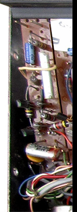
The circuit boards were hinged, allowing top and bottom access for ease in service (see photo at left).
The circuit boards were hand wired to the power supply, controls and jacks. A removable steel lid on the preamp chassis shielded the circuitry from electrical interference.
|
|
|
 Distortion Circuit Board
Thomas P/N 25-5277-2
Distortion Circuit Board
Thomas P/N 25-5277-2
|
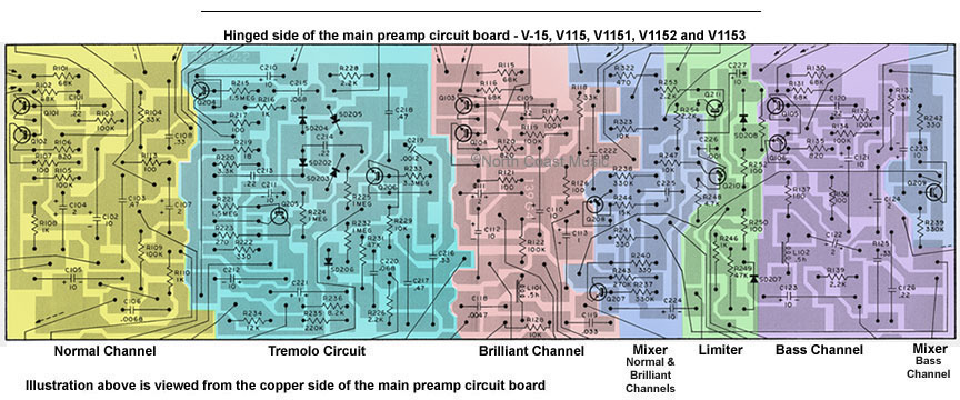
The main preamp circuit board (Thomas p/n 25-5222-2) contained the preamp circuitry for all three channels plus the tremolo, tone control, mixer and "Watchdog" limiter circuitry. A color coded diagram is included above to illustrate the location of the specific circuits on the board.
A second, smaller printed circuit board (Thomas p/n 25-5223-2) in the V-15 and V115 preamp chassis housed the reverb circuit. The reverb "send" and "receive" circuits were both located on this board.
The V-15 and V115 Viscount amp heads included two effects foot pedals. The first was a two button pedal that remotely controlled the reverb and tremolo circuits. This pedal had a three conductor TRS (stereo) 1/4" plug. The second pedal had a single foot switch that remotely activated the MRB ("Mid Resonant Boost") circuit. The MRB pedal had an RCA style plug.
MRB was located in the "Brilliant" channel and boosted mid response at one of three user selectable frequencies: 450 hz, 600 hz or 750 hz.
The foot switch for the MRB circuit activated an electro-magnetic mechanical relay (Thomas p/n 69-1-1) located inside the preamp chassis to initiate the effect. An audible "click" could be heard from the relay within the chassis whenever the MRB foot switch was actuated.
|
 Reverb Circuit Board - Thomas Part Number 25-5223-2
|
The V1151, V1152 and V1153 Viscount Replaces the V-15 and V115
 |
The V1151 and V1152 Vox Viscount amplifiers hit the market in mid 1966, ending the brief six month run for the V-15 and V115 Viscount models at Vox.
The features and most of the circuitry of the V1152 Viscount were identical to the V115. The V1152 featured a new three button foot switch to remotely control reverb, tremolo and MRB.
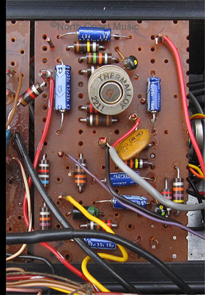
The V1151 added a "Distortion Booster" (fuzz tone) located on a third, narrow circuit board in the preamp chassis. A picture of this fuzz circuit board is seen above and at left. Controlled in a similar fashion to the MRB circuit in the V-15/V115 Viscount, the
|
| Distortion Booster circuit was engaged by an electro-magnetic mechanical relay actuated by the foot switch. The photo shown at near left shows these two relays. The left relay controlled the MRB circuit, the right the Distortion Booster. The relays were located at the bottom of the chassis beneath the controls for the "Normal" channel. |
Vox provided no control panel switch or control for the Distortion Booster. It was actuated exclusively from the four button foot switch included with the amplifier.
Even though the V1152 model Viscount did not officially include the "Distortion Booster" feature, my research suggests that both the Distortion Booster circuit board and relay may have been included in the circuitry for the model. The fuzz feature simply was not accessible with the three button foot switch Vox provided with the V1152.
The 1967 catalog introduced the V1153 Viscount. It included the Distortion Booster circuit, an "E" tuner, a four button footswitch and a closed back. The V15, V115, V1151 and V1152 Viscount models all had open backs.
|
 |
Watchdog
The Westminster, Essex Bass, Viscount, Buckingham, Sovereign, Buckingham, and Super Beatle amplifiers all included the "Watchdog" audio limiter circuit. The 1967 US Vox catalog proudly prolaimed that "Watchdog lets you to blast clearly without overloading. Play at maximum power with optimum tonal quality. When compared with other amplifiers, Vox amps with Watchdog give more usable power, watt for watt, than others of even higher power rating."
|
|
"Watchdog" was an audio limiter circuit designed to prevent the preamp signal level from increasing beyond a factory preadjusted point. As the amplifier reached the level where distortion would occur, the Watchdog circuit would restrict the output level of the preamp to keep the audio signal clean. The Watchdog circuit didn't actually increase the total output of the amplifier, it simply allowed the amplifier to work closer to the maximum undistorted audio output.
A chassis mounted threshold control adjusted the point where the Watchdog circuitry capped the maximum output from the preamp. Click here for the Watchdog limiter circuit factory calibration procedure.
Viscount Reverb Pan
The full length, medium delay reverb pan for the V15, V115, V1151, V1152 and V1153 Viscount was mounted horizontally to a panel that divided the electronics of the amplifier from the speakers. The Thomas replacement part number for the original two spring reverb pan was 23-5002-2. For those seeking to purchase a replacement pan, the modern Accutronics replacement part number is 4FB2A1C.
 |
E-Tuner
Thomas Organ added an "E-Tuner" reference pitch generator (sort of an electronic pitch pipe) to later V1151. V1152 and V1153 Viscount amps. Earlier amps with the E-Tuner circuit included a rotary switch to operate the feature. A slide switch was used in later production. The circuit was mounted to the upper left corner of the head cabinet (see photo at left). The output level of E-Tuner was adjusted by the Bass channel volume control.
The Thomas Organ/Vox service manual stated that the E-Tuner circuit was "adjusted at the factory to a frequency of 323.628 cycles, the true pitch of the high "E" string on a six string guitar."
If a serviceman neglects to reconnect the E-Tuner to the preamp after service, the Bass channel will be dead.
|
|
Buckingham Rotary Power Switch
The Viscount amp used a rotary power switch (Thomas p/n 69-5202-2) that was custom manufacured for Thomas Organ by Clarostat. This switch has caused a few service issues, so let's take a brief look at how it works.
The switch had three positions: "Off," "Standby" and "Operate." The switch also had three individual circuits. The main power switch circuit was located in the back of the switch assembly and supplied 120 VAC to the amp. A second circuit supplied 28 VDC to the red and green pilot lamps. A third circuit completed the circuit between the power amp and the speakers.
When the switch was rotated from the "Off" position to "Standby," the main power switch turned on the AC power to the amplifier. The pilot lamp circuit in the power switch illuminated the green Standby pilot lamp. While in the Standby mode, the switch did not complete the circuit from the power amp to the speakers, allowing the amp to be powered up without hearing a turn-on "thump."
|

|
 |
When the power switch was rotated from "Standby" to "Operate," the main power switch continued to supply AC power to the amp. The "Standby" pilot lamp was extinguished and the red "Power"pilot lamp illuminated. Lastly, the connection between power amp and speakers was completed, enabling the amp for performance.
It is not unusual for the phenolic wafer in the rotary power switch that completed the connection from the amp head to the speaker cabinet to snap off and break. Such damage to the power switch was ironically the result of prior amp service. The damage can happen if the two conductor plug that joined the wires coming from the phenolic speaker wafer on the power switch to the XLR speaker output jack is not disconnected when removing the back. If one neglects to disconnect this plug, a tug on the removable back panel can exert enough pressure on the speaker wafer of the power switch to cause it to fracture.
At left is a photo of the three position power switch that has lost the phenolic wafer that controls the speaker standby function.
As replacements for this custom made rotary switch are unavailable, the easiest solution for this problem is to remove the
|
|
|
|
two speaker wires (brown wires with white stripes) from the broken portion of the rotary switch and connect them together. Unfortunately, this eliminates the speaker standby circuit but it restores function to the amp while retaining factory stock appearance.
|
3_Footer

Photos and editorial content courtesy Gary Hahlbeck
Any and all material presented herein is protected by Copyright.
© 1998 - 2026 The Vox Showroom, all rights reserved
The images and editorial content in this web site may not be copied or reproduced
in online auction sites such as eBay, Reverb and Craig's List. Sellers may provide a link
to the Vox Showroom web site if they wish to refer to this copyrighted material.
|
URL: https://www.voxshowroom.com/us/amp/v1151_preamp_hood.html
|
| |