| The circuitry for the VT100 was mounted on two circuit boards. The upper circuit board was mounted under the control panel and contained all of the REMS (Resonant Structure and Electronic Circuit Modeling System) preamp circuitry. This included the volume, treble, and bass controls along with the digital processing chips for effects such as reverb, echo, chorus, flange, tremolo and amp modeling. The upper circuit was held in place by the control nuts. There are no consumer serviceable parts in the preamp circuitry. The VT100 introduced a number of feature and control enhancements over the AD100VT it replaced. The number of amp models was increased from 11 in the AD100VT to 22 in the VT100. A separate reverb control was added along with sixty-six preset programs, twenty-two "song preset" programs and the capacity to save eight end user programs.
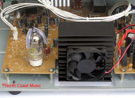
The lower circuit board was mounted to the floor of the chassis and contained the power supply and Valve Reactor power amp circuitry. The 12AX7 tube for the Valve Reactor power amp was located near the edge of the circuit board away from the control panel and held in place with a spring loaded clip. The 100 watt RMS solid state portion of the Valve Reactor circuit was housed on a single, integrated chip that was mounted to a fan cooled aluminum heat sink.
The close up picture of the power amp board (lower right) reveals some unrealized plans for the VT power amplifier circuit. The circuit board appears to be designed to incorporate a second tube socket and supporting circuitry. I spoke to several sources at Vox regarding this subject, but no one seemed to know what was planned. Perhaps Vox was considering a stereo VT amp using a fully populated version of this Valve Reactor power amp board.
|