|
The Vox AC1/15, the production version of Dick Denney’s original 15-watt tube guitar amplifier, was introduced in early 1958. It was subsequently replaced by the second-generation AC/15, designated “AC/15 Amplifier Circuit No. 2” and documented in Jennings schematic OS/005, dated December 5, 1959. This revision remained in production for less than five months before being replaced by a further redesign designated “AC/15 Amplifier Circuit No. 3,” documented in Jennings schematic OA/031, dated April 29, 1960. The amp featured on this page, serial 4097, was built utilizing the OA/031 design. The date "30 AUG 1960" was stamped in ink on the bell of the output transformer (see Fig.1 below). |
|
Summary of Changes
Vox AC/15 Amplifier No. 3
| ● |
Circuit is depicted on Jennings schematic OA/031 dated April 29, 1960 |
| ● |
Redesigned preamp circuit |
| ● |
AC.15 Bass model introduced |
| ● |
Vibravox components no longer concealed |
| ● |
Vibrato function restored to Vibravox effect |
| ● |
First use of the Celestion G12 Blue Alnico |
|
|

Fig 1 - Date Stamp - AC.15 No. 3 Amplifier |
|
Contempo Chassis
Originally implemented for the AC/15 No. 2, the Contempo chassis design was carried forward into the AC.15 No. 3 as well (see Fig. 2).
Vox engineer Derek Underdown developed the Contempo chassis to address several key design objectives: simplify chassis access for factory assembly and servicing, accommodate the ever expanding number of circuit components in Vox amps, improve electrical isolation of the preamplifier from interference generated by the power supply and enhance weight distribution by positioning the mains and power transformers at opposite ends of the chassis.
The Contempo chassis was comprised of a stamped steel base housing the power supply and amplifier output stages plus a vertical, "L" shaped folded aluminum section that housed the preamp circuits and control panel. |
| Because aluminum is non-magnetic and highly conductive, this upper section helped shield the sensitive preamp stages from stray electromagnetic interference and hum eminating from the mains and output transformers just below. At the same time, it provided an effective deterence to high-frequency oscillation. |
The Contempo chassis was mounted on a plinth, or “slider board,” constructed from seven-ply 9 mm (3/8-inch) plywood. The board rested on rails fitted inside the amplifier cabinet, allowing the chassis to slide in and out like a drawer for convenient access to the tubes and preamp circuitry.
While introduced for the AC/15, the Contempo chassis design was subsequently adapted by Vox for use in the AC-10, AC-10 Twin, AC-15 Twin, AC-30, AC-50, and AC-100 models.
Changes in the OA/031 AC.15 Amplifier Circuit No.3
The AC/15 No.3 circuit, detailed in the Jennings schematic OA/031 (see Fig. 4), brought significant revisions to the power supply, power amp/phase inverter, preamp and Vibravox circuits when compared |
|

Fig 2: AC.15 Contempo Chassis
|
to the previous schematic, OS/005, dated December 4, 1959. Download a complimentary copy of the OA/031 AC.15 schematic from the Vox Showroom by clicking here.
Power Supply
The purpose of the power supply circuit is to convert the locally supplied AC mains (supply) voltage into suitable operating voltages to power the amplifier. The components required to accomplish this task in the Vox AC.15 No. 3 amplifier are the mains (or power) transformer, EZ81 rectifier tube, filter capacitors and the choke.
Mains Transformer - Primary Taps: The mains, or supply voltages used throughout the world in the early 1960s varied widely. To accommodate these differences, Vox designed the primary (input) side of its power transformers to support five different local supply voltages. The factory schematic for the AC.15 No.3 specified five primary voltage taps: 110 VAC for North America; 160 VAC for a small number of UK municipalities; 200 VAC for parts of London and Hong Kong; 220 VAC for the UK; and 250 VAC for most other regions of the world. A five-position voltage selector on the amplifier's control panel allowed the user to select the appropriate setting for the local mains supply. By comparison, the AC/15 No. 2, which preceded the AC/15 No. 3, offered only three primary voltage options: 200, 230, and 250 VAC. As a result, the AC/15 No. 2 could not be connected directly to the 110–120 VAC power grid of the United States. The AC.15 No. 3 addressed this limitation by adding a 110 VAC primary tap for North America.
Mains Transformer – Secondary Taps: The secondary windings of the mains transformer supplied the voltages required to operate the amplifier’s circuitry. The high-voltage secondary winding, commonly referred to as the B+ supply, was rated at 300 VAC in the AC.15 No. 3. An additional 6.3 VAC secondary winding supplied power to the tube heaters.
B+ Supply Rectification: The AC/15 No. 3 used an EZ81 rectifier tube in conjunction with a CLC (capacitor–choke–capacitor) filter circuit to convert the transformer’s high-voltage AC output into DC for the B+ supply. The filter circuit consisted of two 16 µF, 450 V capacitors and a choke with an inductance range of 10–20 H.
Power Amplifier, Phase Inverter and "Tone Cut" Control
The power amplifier stage of the AC.15 No. 3 was nearly identical to that of the preceding AC/15 No. 2, with one notable exception: the 100-ohm resistors previously connected to the plates of the EL84 output tubes were relocated to their screen grids.
The phase inverter in all three versions of the AC-15 was powered by an ECC83 (12AX7) tube in long tailed pair mode.
The AC.15 No. 3 reverted to the original AC1/15 "Tone" control design by bridging the positive and negative outputs of the phase inverter with a .005 uf capacitor and a 250,000 ohm "Tone Cut" control pot. Because the capacitor only lets treble frequencies cross between the two opposing sides of the phase inverter, those high frequencies cancel each other out when they meet. The 250k "Tone Cut" knob acts like a valve that controls how much of that cancellation happens, allowing the tone to be adjusted from bright to dark.
|
Single Stage Preamp Circuit
All three original Vox AC-15 models (AC1/15, AC15 No. 2, and AC15 No. 3) employed a single-stage preamp circuit. In this setup, each channel ran on just a single preamp tube stage, either a triode or a pentode. Because there weren't any extra preamp tube stages chained together after it, the amp kept a simpler signal path without the extra gain boost or separate bass and treble knobs you'd find in more complex tone circuits. Consequently, the available gain in each channel was determined primarily by the amplification factor (μ) of the preamp tube selected for that channel. Please see Fig. 3 for a summary of these tubes and their amplification factors.
|
|
|
Model |
|
Channel |
|
Tube |
|
Amplification Factor |
|
AC1/15 |
|
Normal |
|
12AX7 |
|
100 |
|
|
|
Vibrato |
|
12AX7 |
|
100 |
|
AC/15 No.2 |
|
Normal
|
|
ECF82 |
|
40 |
|
|
|
Vibrato |
|
EF86 |
|
180 |
|
AC.15 No.3 |
|
Normal
|
|
EF86 |
|
180 |
|
|
|
Vibrato |
|
12AX7 |
|
100 |
|
Fig. 3 - AC1/15, AC/15 No.2 & AC.15 No. 3 Preamp Tubes |
The AC1/15 took the most traditional approach, using a single 12AX7 (ECC83) preamp tube to handle both channels. Because the 12AX7 is a dual-triode tube, Vox simply split the workload—assigning one half to the Normal channel and the other half to the Vibrato channel. Each side was capable of boosting the incoming guitar signal up to 100 times its original strength.
The Vox AC/15 No. 2 featured a complete preamp redesign, replacing the layout of the AC1/15 in favor of an EF86 tube on the Vibrato channel and an ECF82 on the Normal channel.
The EF86 was a pentode tube with an amplification factor of 180, nearly twice the output of the 12AX7 it was replacing. It was commonly found in fifties and sixties high-end hi-fi equipment. In guitar amplifiers, it produced a distinctive tone characterized by sparkling “chime” and rich harmonic content. It also offered remarkable touch sensitivity, allowing players to move from clean to overdriven tones simply by adjusting the guitar’s volume control or picking with greater intensity. Dick Denney was such so fond of the EF86 that he went on to incorporate it into the preamp circuits of several other Vox amplifiers, including the AC4, AC10, and AC30/4.
The ECF82 used in the preamp of the AC15/No. 2 was a different story. This dual-function tube combined both triode and pentode sections in a single envelope. In the AC15/No. 2, the triode section served as the preamp for the Normal channel. With an amplification factor of only 40, it provided relatively modest gain, resulting in a channel that could sound somewhat lifeless. The pentode section, meanwhile, was employed as the modulator for the Vibravox circuit.
For the Vox AC.15 No. 3, Vox shuffled the preamp tubes around—moving the EF86 over to the Normal channel and bringing the 12AX7 back to handle the Vibrato channel. With that final tweak, Vox locked in the AC-15 preamp design—using it to power the rest of JMI's AC-15 and AC-15 Twin production all the way through 1966.
|
|
Component Changes - AC-15 Std vs AC-15 Bass
|
|
Component #
|
AC-15 Standard
|
AC-15 Bass
|
|
C3
|
.01 uf
|
.05 uf
|
|
C6
|
.01 uf
|
0.1 uf
|
| C7 |
.01 uf |
0.1 uf |
| C9 |
.01 uf |
0.1 uf |
| C10 |
.01 uf |
0.1 uf |
| C11 |
.005 uf |
.01 uf |
|
Fig. 4 - Capacitor Substitutions - AC.15 No.3 Bass Amp
|
|
AC-15 Bass Amp
Tucked inside the OA/031 schematic for the Vox AC.15 Circuit No. 3 was the quiet debut of a "Bass" version of the AC-15. Rather than designing a whole new circuit, Vox created the AC-15 Bass simply by swapping out five coupling capacitors along with one additional capacitor in the "Tone Cut" control.
Coupling capacitors do three big jobs in a guitar amp: they carry the audio signal from one stage to the next, block the high DC voltages powering the tubes, and shape the amp's voice by setting where the bass frequencies roll off. When Dick Denney originally voiced the AC-15, he intentionally |
chose coupling capacitor values that rolled off much of the low-end bass, giving the amp its signature bright, "chimey" character. The AC-15 Bass model substituted coupling capacitors with significantly higher uF values in the C3, C6, C7, C9, and C10 positions, giving the amp a deeper bass response. (see Fig. 4 above).
Vox also tweaked the "Tone Cut" circuit, swapping out the standard AC-15's .005 uF capacitor for a larger .01 uF capacitor in the Bass model. This change let the Tone Cut knob reach further down into the midrange, allowing it to shape a wider band of frequencies..
|
Cabinet and Control Panel
The cabinet design of the AC/15 No. 3 was revised to accommodate the new Contempo chassis. Unlike the AC1/15, which featured an isolated “island” control panel cutout, the opening in the AC/15 No. 3 cabinet extended to the rear of the amplifier. This modification allowed the Contempo chassis to slide into the cabinet along internal mounting rails. The cabinet shell was fabricated with finger-jointed, 3/8" baltic birch plywood. The original fiberboard rear panel from the AC1/15 was replaced by upper and lower plywood panels, resulting in an open-back cabinet configuration that also provided storage for the power cable and Vibravox foot switch. The upper rear panel also served to secure the chassis in position. The cabinets were covered in tan vinyl with a black "fishnet" pattern or in a two tone vinyl covering. The black anodized control panel had gold nomenclature.
Speaker
The AC/15 No. 2 was equipped with a 12" Goodmans Audiom 60 speaker rated at 15 watts RMS and 15 ohms. |
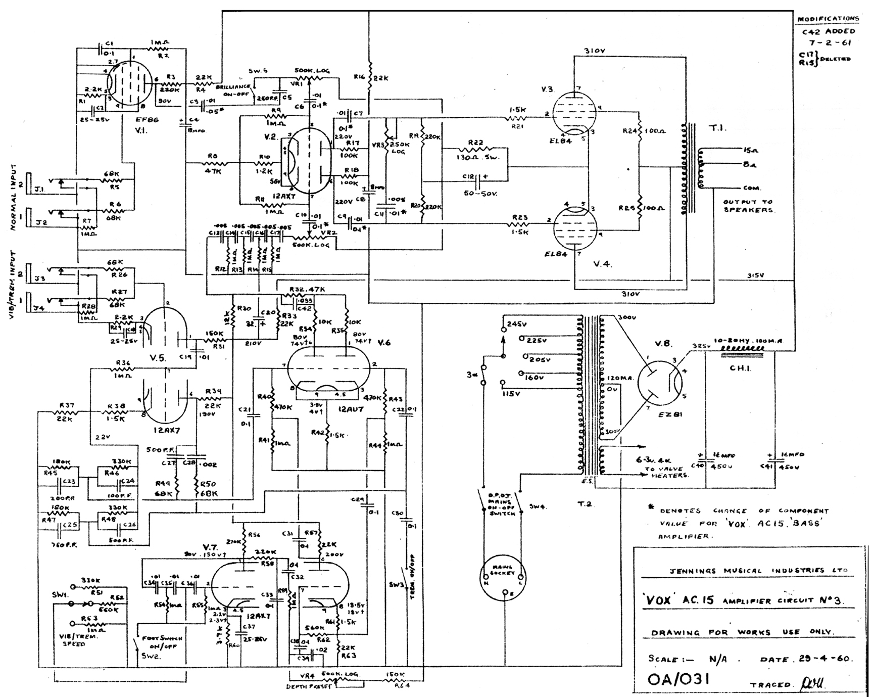 Fig. 5 - Jennings Musical Industries OA/031 factory schematic for AC.15 No. 3 circuit
3_Footer

Photos and editorial content courtesy Gary Hahlbeck
Any and all material presented herein is protected by Copyright.
© 1998 - 2026 The Vox Showroom, all rights reserved
The images and editorial content in this web site may not be copied or reproduced
in online auction sites such as eBay, Reverb and Craig's List. Sellers may provide a link
to the Vox Showroom web site if they wish to refer to this copyrighted material.
|
URL: https://www.voxshowroom.com/uk/amp/ac15-1960.html
|