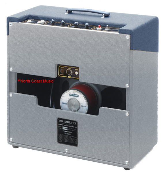
Vox introduced the AC1/15, the production version of Dick Denney's original 15 watt tube guitar amp, in the spring of 1957. A second generation version of the AC1/15, the "AC/15 Amplifier Circuit No. 2" was introduced on Jennings schematic OS/005 dated December 5, 1959. This revised circuit was utilized on AC-15 amps produced from late fall 1959 through late spring 1960.
Along with the circuit revisions documented in schematic OS/005, Vox introduced the “Contempo” chassis design, a revised control panel layout and a cabinet finished in two-tone vinyl on the second-gen AC/15. |
|
Summary of Changes
Vox AC/15 Amplifier No. 2
| ● |
Circuit is depicted on Jennings schematic OS/005 dated December 4, 1959 |
| ● |
Introduction of the Contempo chassis |
| ● |
First use of slider boards for chassis mounting |
| ● |
Changes to the second generation circuit |
| ● |
Vibravox reduced to a tremolo effect |
| ● |
Open Back Cabinet, Two Tone Vinyl |
|
|

Fig 1 -AC-15 "Contempo" chassis |
|
Contempo Chassis
The chassis of the original AC1/15 was constructed on a rectangular steel pan. Vox engineer Derek Underdown developed the Contempo chassis (see Fig. 1) to overcome limitations of the original design. The new layout allowed the mains and power transformers to be mounted horizontally on the chassis base rather than suspended vertically, alleviated circuit overcrowding, improved weight distribution, and simplified access for servicing.
The ingenious JMI Vox AC-15 Contempo chassis design combined a horizontal steel base, housing the power supply and output amplifier circuitry, with a vertical aluminum section that accommodated the preamp circuitry and control panel. Separating the power supply and output amp components from the preamp circuitry alleviated the overcrowding that had characterized the original AC1/15 chassis.
The steel chassis base provided structural strength while helping to shield the preamp from electromagnetic interference generated by the high-voltage power supply and output |
amplifier sections. It also provided the opportunity to mount the mains and output transformers horizontally on opposite ends of the chassis to promote better weight distribution. Using aluminum for the vertical preamp section offered additional benefits. Aluminum is lighter in weight and generally less susceptible than steel to nterference from nearby power supply and output stage components. This helped reduce unwanted hum and oscillation while improving the electrical isolation of the preamp. Although aluminum is significantly lighter than steel, it is not as strong. Brackets mounted to the top of the power and output transformers strengthened and supported the upper area of the aluminum section of the chassis.
The Contempo chassis was mounted on a plinth, or “slider board,” constructed from seven-ply 9 mm (3/8-inch) plywood. The board rested on rails fitted inside the amplifier cabinet, allowing the chassis to slide in and out like a drawer for convenient access to the tubes and preamp circuitry.
While introduced for the AC/15, the Contempo chassis design was subsequently adapted by Vox for use in the AC-10, AC-15 Twin, AC-30, AC-50, and AC-100 models.
Changes in the OS/005 AC/15 Amplifier Circuit No.2
The AC/15 No.2, detailed in the Jennings schematic OS/005 (see Fig. 3 below), introduced significant revisions to the mains cable, power supply, output stages, preamp and Vibravox circuits when compared to the original AC1/15 schematic, dated March 4, 1958.
Mains Cable
Unlike the AC1/15 and its detachable mains cable, the AC/15 No.2 utilized a permanently attached power cord which could be stored inside its new open-back cabinet for transit.
Power Supply: Mains Transformer and B+ Supply Rectification
Mains Transformer - Primary Taps: The schematic for the AC1/15 mains transformer listed primary (wall voltage) taps of 110 VAC, 130 VAC, 200 VAC, 220 VAC and 250 VAC with a five position voltage selector. The schematic for AC/15 No.2 offered only three primary voltage taps: 200 VAC, 230 VAC, 250 VAC with a three position rotary voltage selector.
Mains Transformer - Secondary Taps: The AC1/15 Haddon power transformer featured three secondary voltage outputs. The main high-voltage tap provided 350 VAC, an aggressive choice considering EL84 output tubes carry a maximum safe B+ rating after rectification of 300 VDC. The remaining two taps supplied 6.3 VAC for the standard tube heaters and 5 VAC to run the filament of the 5Z4 rectifier tube.
With the AC/15 No.2, the transformer was simplified to two secondary taps: a 300 VAC high-voltage supply and a 6.3 VAC filament heater supply. Though lower than its predecessor, the 300 VAC tap still hit the upper safety limits for an EL84. The AC/30 No.2 design swapped the original 5Z4 rectifier tube in the AC1/15 for an EZ81, removing the need for a dedicated 5 VAC heater tap
B+ Supply Rectification: The B+ voltage of the AC1/15 was rectified by a 10H choke and two 16uf 450V capacitors in a pi filter network. The AC/15 No.2 utilized a similar circuit having a 8H choke and two 16uf 450V capacitors.
Output Stage and Phase Inverter
The output stages of the AC1/15 and AC/15 No.2 were virtually identical with both power amplifiers utilizing a pair of cathode-biased EL84 tubes. The only circuit modification for the AC/15 No.2 was the addition of 100 ohm plate resistors on the EL84 tubes. Denney and Underdown probably added these resistors as a practical measure to scale back the B+ voltage to a safer range.
The phase inverter in both amps was powered by an ECC83 (12AX7) tube in long tailed pair mode. The AC/15 No.2 phase inverter circuit was identical to that of the AC1/15 with the sole exception of removing the 250k pot and .005uf capacitor that straddled the outputs of the AC1/15 phase inverter stage. These components enabled the global "Tone Cut" control on the AC1/15.
|
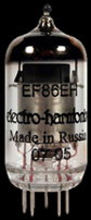
EF86 Tube |
|
Preamp Circuit
The original 15-watt amplifier designed by Dick Denney, the AC1/15, featured a 12AX7 tube in its preamp section. As a dual-triode tube, the 12AX7 served both channels, with one triode dedicated to the “Normal” channel and the other to the “Vibrato” channel. Its amplification factor of 100 enabled it to increase the strength of the incoming signal by as much as 100 times.
The redesigned preamp circuitry for the AC/15 No.2 replaced the 12AX7 with an EF86 tube in the "Vibrato" channel and an ECF82 tube in the "Normal" channel.
The EF86 was a pentode tube with an amplification factor of 180, nearly twice the output of the 12AX7 it was replacing. It was commonly found in fifties and sixties high-end hi-fi equipment. In guitar amplifiers, it produced a distinctive tone characterized by sparkling “chime” and rich harmonic content. It also offered remarkable touch sensitivity, allowing players to move from clean to overdriven tones simply by adjusting the guitar’s |
volume control or picking with greater intensity. Dick Denney was such so fond of the EF86 that he went on to incorporate it into the preamp circuits of several other Vox amplifiers, including the AC4, AC10, and AC30/4. Unfortunately, the EF86’s high amplification factor also made it more prone to microphonic feedback, a problem that was particularly noticeable in the AC30/4.
The ECF82 used in the preamp of the AC15/No. 2 was a different story. This dual-function tube combined both triode and pentode sections in a single envelope. In the AC15/No. 2, the triode section served as the preamp for the “Normal” channel. With an amplification factor of only 40, it provided relatively modest gain, resulting in a channel that could sound somewhat lifeless. The pentode section, meanwhile, was employed as the modulator for the Vibravox circuit.
Two 1/4" input jacks were provided for each channel. The input jacks for Channel 1 or the "Normal" channel had black nuts while the input jacks for Channel 2 or the "Vibravox" channel had white.
Unlike the AC1/15 which employed a single global tone control, the AC/15 No. 2 circuit featured independent passive tone controls for each channel. These controls attenuated the high-frequency response without affecting the low-frequency response.
|
Vibravox Circuit
A print advertisement published in the July 26, 1958, issue of Melody Maker magazine announced that the recently introduced Vox Vibravox effect was now available as a built-in feature of the AC1/15 and AC2/30 amplifiers, as well as in a standalone unit. Vibravox was a tube powered effect that offered three speeds of vibrato and three speeds of tremolo.
Vox took considerable measures to protect the proprietary design of the Vibravox circuit, encapsulating portions of the circuitry in round metal enclosures filled with epoxy to prevent others from examining and reproducing the design. Somewhat ironically, Vibravox was itself derived by Vox from a circuit used in Wurlitzer home organs. |
|

Fig. 2 - Vibravox Controls On AC/15 No.2 Upper Rear Panel |
With the introduction of the AC/15 No. 2 which also incorporated the Vibravox effect, one might reasonably expect the amplifier to retain both vibrato and tremolo capabilities. However, this was not the case. Vibrato was eliminated, leaving Vibravox functioning exclusively as a tremolo effect. The Vibravox controls were also relocated from the control panel to the upper rear panel of the amplifier. In place of the original three-position rotary speed selector, the AC/15 No. 2 featured a continuously variable speed control and a push-button control for modulation depth. Vox continued its practice of concealing the Vibravox circuitry by housing its components in a separate subchassis assembly encapsulated in epoxy resin and secured to the inside of the amplifier’s upper rear panel. The subchassis was electrically connected to the main chassis through a nine-pin Noval connector. A remote foot switch activated the tremolo effect. The yellow highlighted section of the AC/15 No. 2 schematic shown in Fig. 3 illustrates the circuit configuration of the revised, tremolo only Vibravox effect.
Cabinet and Control Panel
The cabinet design of the AC/15 No. 2 was revised to accommodate the new Contempo chassis. Unlike the AC1/15, which featured an isolated “island” control panel cutout, the opening in the AC/15 No. 2 cabinet extended to the rear of the amplifier. This modification allowed the Contempo chassis to slide into the cabinet along internal mounting rails. The cabinet shell was fabricated with finger-jointed, 3/8" baltic birch plywood. The original fiberboard rear panel from the AC1/15 was replaced by upper and lower plywood panels, resulting in an open-back cabinet configuration that also provided storage for the power cable and Vibravox foot switch. The upper rear panel also served to secure the chassis in position. The cabinets were covered in tan vinyl with a black "fishnet" pattern or in a two tone vinyl covering. The black anodized control panel had gold nomenclature.
Speaker
The AC/15 No. 2 was equipped with a 12" Goodmans Audiom 60 speaker rated at 15 watts RMS and 15 ohms. |
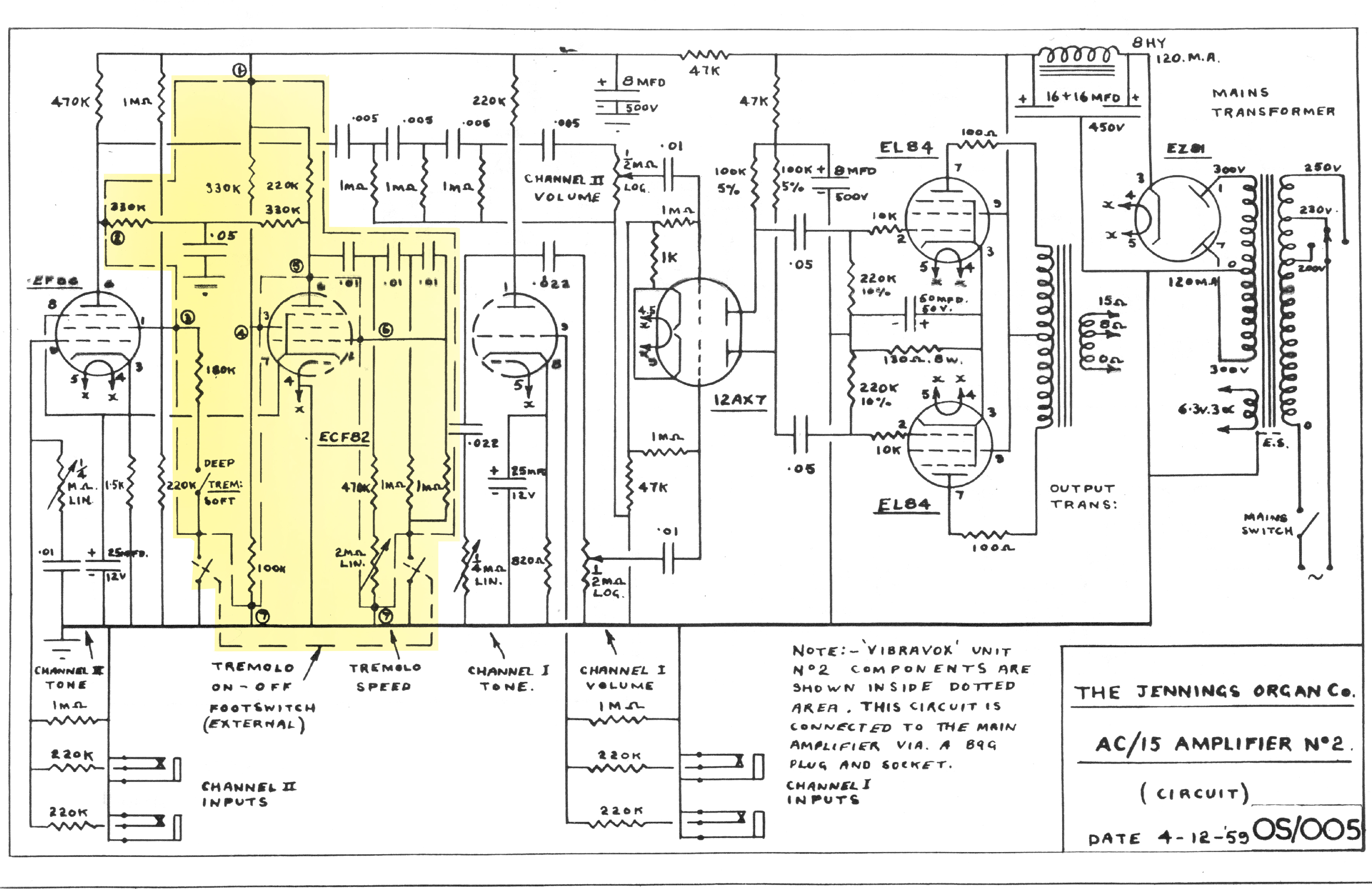 Fig 3 -AC/15 No.2 factory schematic with Vibravox components highlighted in yellow
3_Footer

Photos and editorial content courtesy Gary Hahlbeck
Any and all material presented herein is protected by Copyright.
© 1998 - 2026 The Vox Showroom, all rights reserved
The images and editorial content in this web site may not be copied or reproduced
in online auction sites such as eBay, Reverb and Craig's List. Sellers may provide a link
to the Vox Showroom web site if they wish to refer to this copyrighted material.
|
URL: https://www.voxshowroom.com/uk/amp/ac15-1958.html
|