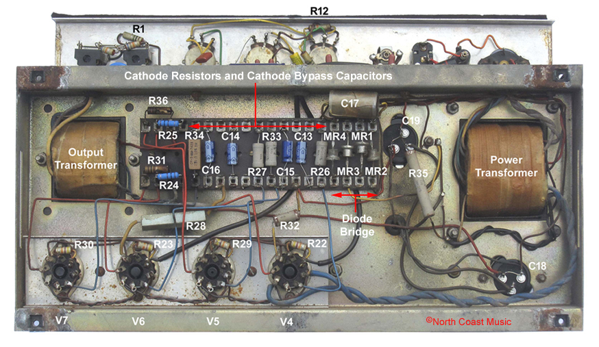
The photos near the top of the page reveal that four 270Ω cathode resistors (R26, R27, R33 and R34) and four cathode bypass capacitors (C13, C14, C15 and C16) are located on the lower tag strip of the "80-100 Watt" AC-100 MkI circuit. Two 330kΩ bias resistors (R20 and R21) are located on the upper tag strip as part of the phase inverter circuit.
It is easy to spot if an AC-100 head has the cathode bias circuit by looking through the ventilation screen on the bottom of the amplifier. If the lower tag strip has four matching resistors and capacitors, it is a cathode biased amp.
JMI dropped the cathode biased AC-100 head in June 1965 in favor of the fixed bias
OS/036 AC100/2 Amplifier circuit.
Diode Rectified Power Supply
The AC-100 "80-100 Watt" power supply circuit included a power transformer, a rotary voltage selector, two fuses, four BY100 silicon diodes, two large filter or "smoothing" capacitors and a 10H 250 mA choke.
The AC-100 "80-100 Watt" chassis was equipped exclusively with a Woden 72191 power transformer. The primary, or input side of the transformer had five taps. When combined with the control panel mounted rotary voltage selector, these taps allowed the AC-100 to accommodate the various mains voltages throughout the world. A 3A control panel mounted fuse (FS1) protected the primary side of the power transformer from current surges.
The secondary side of the power transformer had three windings. A 350 VAC winding powered the B+ circuit. One center-tapped 6.3 VAC winding powered the tube filaments for the EL-34 output tubes while a second center-tapped winding powered the preamp tube filaments.
The AC-100 head was the first tube amp design from Vox without a tube rectifier. The AC-100 utilized a bridge of four BY100 diodes (M1 - MR4) for DC rectification. AC-100 amps with the "80-100 Watt" circuit were normally equipped with a horizontally oriented 10H 250 mA Woden choke (p/n #79213). JMI changed to a vertically oriented Woden 19H 100mA choke (p/n #76854) in 1965, as noted on the later schematic for the AC-100/2 amplifier. The "80-100 Watt" AC-100 chassis shown above was built in 1964 and had the early Woden 72191 power transformer but the later 76854 19H Woden choke.
The choke was straddled by two 100uf filter capacitors (C18 and C19) to smooth the AC ripple in the 430 VDC B+ power supply. An internally mounted 1A fuse protected the B+ power supply from damage caused by internal short circuits.

|
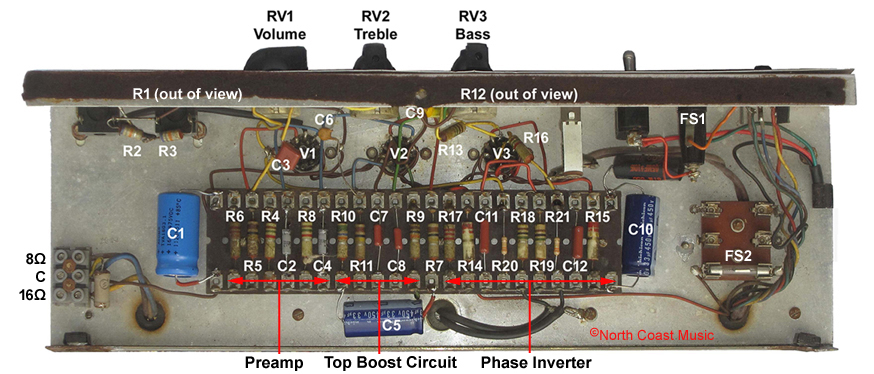
Preamp Circuit
The preamp section of the AC-100 "80-100 Watt Amplifier Circuit" included two tubes, V1 and V2.
The input jacks connect to V1, a 12AU7 (ECC82) tube. The 12AU7 is a dual triode tube with a gain factor of 17. This means that either of the ECC82 triodes has the potential to amplify the signal input seventeen times. Vox used only one of the two triodes for the first gain stage of the AC-100 preamp, the second triode was not utilized.
V2 was a 12AX7 (ECC83), another dual triode tube. The triodes of the 12AX7 have a gain factor of 100, meaning they will amplify the signal input one hundred times. In the AC-100 circuit, the first triode was used as an additional preamp gain stage. The second triode powered the "Top Boost" tone controls (shown at left), identical to the circuit in top boosted AC-30 amps. |
Phase Inverter
All amplifiers using a "push-pull" circuit design, such as the AC-100, need to have a phase inverter circuit. The phase inverter converts the audio signal from the preamp into two equal but opposite waveforms. Each waveform feeds one side of the push-pull output amplifier. The output tubes then connect to the primary side of the output transformer where the original and inverted signals emerge as a single amplified signal. Tube V3, a 12AU7, powers the AC-100 phase inverter circuit.
Four-Pin XLR Power Cable
The AC-100 utilzed a detachable power cord that featured a standard regional AC plug on one end and a four-pin female XLR connector on the other. While this may not be the case on your amplifier, Vox normally connected the "Neutral" or white wire from the power cable to pin one of the four-pin XLR plug. The "Hot" or black wire was connected to pin four of the four-pin XLR plug. The ground (green) wire was connected to pins 2 and 3 of the four-pin XLR jack. |
|
WARNING - There is no way to know if your Vox amplifier will match this wiring scheme. Please consult a trained professional service technician for assistance with the power cable. The Vox Showroom accepts no responsibility for personal injury or damage to your amplifier from this information. |