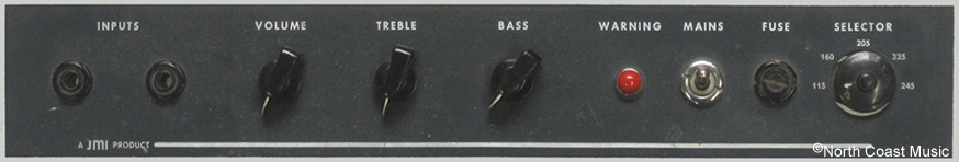
Gray Control Panel
A majority of Vox amps produced by JMI between 1964 and 1967, including the AC-100/2 shown on this page, had "etched and filled" aluminum control panels.
The etching process used a strong caustic chemical to cut into the foreground area of the aluminum control panel. The etched aluminum foreground was then filled with screen printed gray paint to create a level and durable finish.
|
The AC-100/2 Chassis
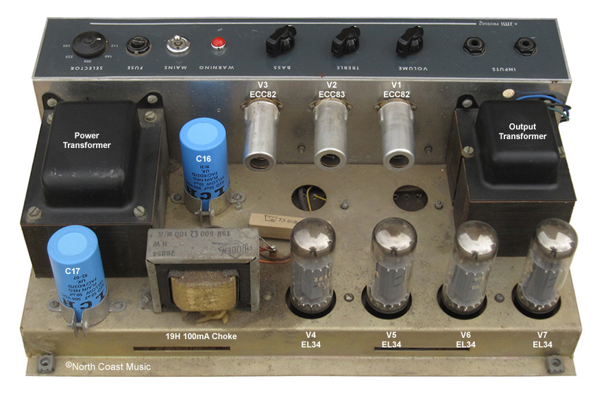
The chassis design of the JMI Vox AC-100/2 combined a pressed steel horizontal base with a vertical assembly made of aluminum.
The steel base of the chassis supported the power supply and output amp sections of the AC-100. The use of steel in the chassis base not only provided strength but also electronically isolated the high voltage (and hum producing) section of the power supply and output amp from rest of the amplifier. The power transformer and output transformers were located at opposite ends of the chassis base to provide proper balance.
|
|
|
 |
|
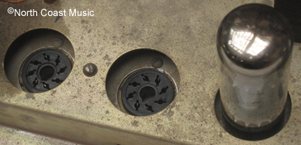
The sockets for the EL34 power tubes were suspended in a tray below the top of the steel base (see photo above). This improved air circulation inside the cabinet and provided additional clearance between the cabinet and the tops of the power tubes.
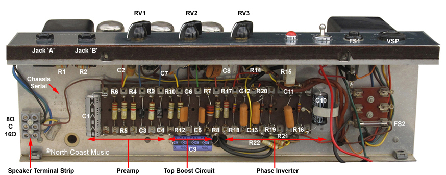
The vertical aluminum upper chassis enclosed the preamp circuitry and secured the control panel. Aluminum is even less likely than steel to pick up hum and oscillations (eddy currents) from the power supply and output amp section of the amp. This served to further electronically shield the preamp from the power supply.
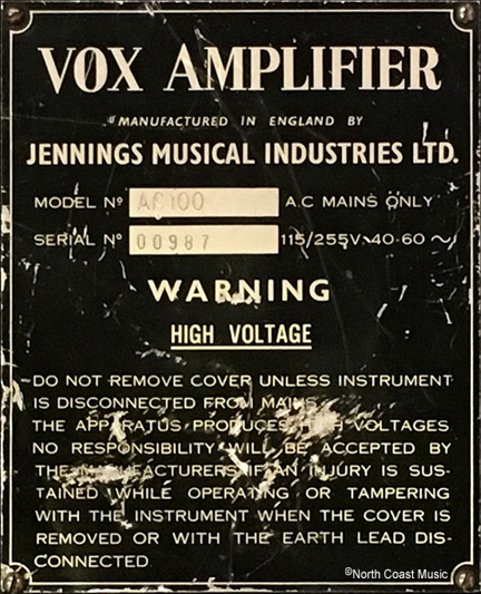
Burndepts, the metal working firm that formed the chassis for the AC-100, stamped a serial number in the inside upper chassis near the speaker terminal strip (see photo at left). The chassis serial was not the same as the serial stamped on the rear panel ID plate. The amp shown in this page was stamped #00987 on the external ID plate but #1776 inside the upper chassis. |
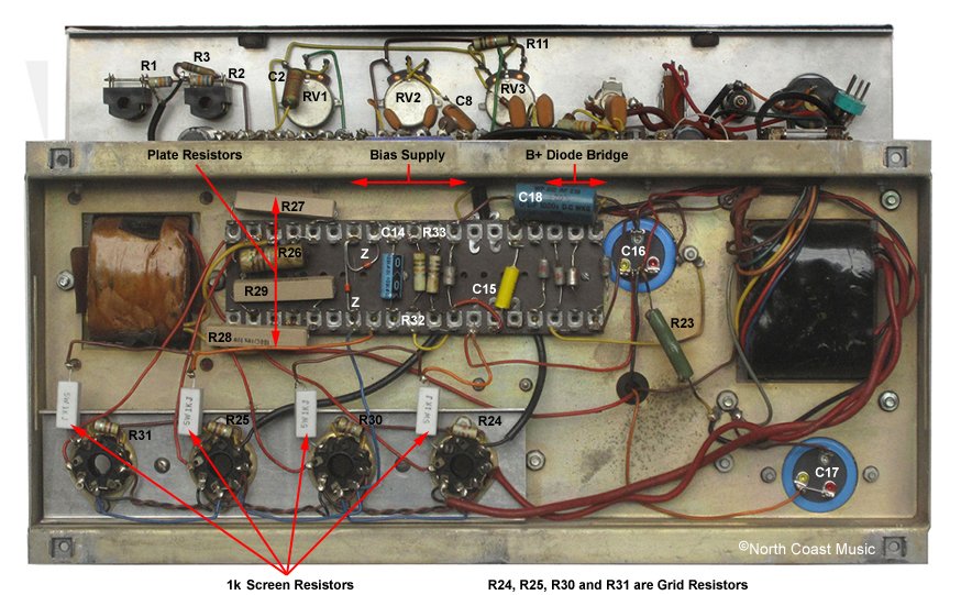
Fixed Bias NFB Output Stage
Bias refers to the amount of current that flows through a tube. If too much current flows through a tube, the tube may run red hot and fail prematurely. If too little current flows through the tube, the tone from the amp will be bland and lifeless. While the earliest AC-100 amps had a
cathode or "self biasing" output circuit, the AC-100/2 had a
fixed bias output circuit.
The cathodes of the output tubes of a cathode bias output circuit connect to ground through a
cathode resistor and most often also through a
bypass capacitor.
Screen resistors connect the
screen grids of the output tubes to the B+ power supply. Cathode biased amps do not have an adjustable bias supply. Bias is self-regulated by the relationship of the gain and frequency of the input signal with the cathode and screen resistors.
In a fixed bias output circuit, the cathodes of the output tubes are connected directly to ground. An adjustable
bias supply provides a small negative voltage to the
control grid of the output tube. In simplest terms, this bias voltage starts the flow of electrons from the cathode to the plate of the output tube, providing amplification. While most fixed bias amplifiers include a trim pot to manually adjust the bias voltage of the output tubes, the AC-100/2 included a unique circuit that eliminated the need for this manual adjustment.
This AC100/2 tapped one half of the B+ power supply to provide a 210VDC source for the bias supply. The 210 volt bias supply voltage was further conditioned by passing it through a BY100 diode, an 8uf filter capacitor (C14), two 10k resistors (R32 and R33) and a pair of zener diodes. Zener diodes have the unique property of regulating the amount of voltage that they pass. The zener diodes in the AC-100/2 were calibrated to limit the negative bias voltage to -35 VDC. This biased the EL34 output section without the need for manual adjustment.
Like the AC-30, the output stage for JMI Vox AC-100 does not use negative feedback (NFB). Amps with NFB take a small amount of the signal from the output transformer and direct it back into the preamp to improve fidelity and reduce distortion. Amps without NFB, such as the Vox AC-30 and AC-100, offer higher gain and a smoother transition from clean to overdrive.
Diode Rectified Power Supply
The AC-100/2 power supply circuit included a power transformer, a rotary voltage selector, two fuses, a bridge of four BY100 silicon diodes, a CZ4 Brimistor, two large filter or "smoothing" capacitors and a Woden 19H 100 mA choke.
The primary, or input side of the power transformer had five taps. When combined with the control panel mounted rotary voltage selector (VSP), these taps allowed the AC-100 to accommodate the various mains voltages throughout the world. A 3A control panel mounted fuse (FS1) protected the primary side of the power transformer from current surges.
The secondary side of the power transformer had three windings. A 360 VAC 595 mA winding powered the B+ circuit. One center-tapped 6.3 VAC, 6.5A winding powered the tube filaments for the EL-34 output tubes while a second 6.3 VAC, 2A center-tapped winding powered the preamp tube filaments and indicator lamp. This separation of the preamp and output tube heater windings is quite unusual. It virtually elminated any chance of interaction between the preamp and output amp stages. I cannot suggest another guitar amplifier that used this dual heater design.
The AC-100 was the first tube amp design from Vox without a tube rectifier. The AC-100/2 utilized a bridge of four BY100 diodes for B+ rectification. The remaining AC ripple in the B+ power supply was smoothed by a 19H 100 mA choke that was straddled by two dual element 50 uf filter capacitors (C16 through C19). Each dual element filter capacitor was wired in parallel to yield a 100uf capacitance. An internally mounted 1A fuse (FS2) protected the B+ power supply from damage caused by internal short circuits.
|
The schematic for AC-100/2 called for a Brimar CZ4 "Brimistor" in the B+ power supply. A Brimistor was a thermally sensitive resistor encased in a heating element. It was designed to guard against a potentially harmful "switch-on" current surge in the amp. The Brimistor was mounted to the top of the chassis base.
The electrical resistance of the Brimistor was highest when the amp was cold. This allowed the Brimistor to have the greatest effect of limiting "in-rush" current as the amp was first turned on. As the amp warmed, the heating element inside the Brimistor caused the resistance of the thermally sensitive resistor to drop. After 30 seconds, this drop in resistance allowed the Brimistor to pass the full operating B+ voltage to the circuit.
Over time, failures of the CZ4 Brimistor became common. This would disable the B+ power supply of the amplifier. Some amp techs replaced the troublesome Brimistor with a fixed 7.5 ohm 25 watt resistor, as shown in the photo at left. The resistor simulated the resistance of the Brimistor at operating temperature.
|
|
 |

|
Preamp Circuit
The preamp section of the AC-100/2 included two tubes, V1 and V2.
The input jacks connect to V1, a 12AU7 (ECC82) tube. The 12AU7 is a dual triode tube with a gain factor of 17. This means that either of the ECC82 triodes has the potential to amplify the signal input seventeen times. Vox used only one of the two triodes for the first gain stage of the AC-100 preamp, the second triode was not utilized.
V2 was a 12AX7 (ECC83), another dual triode tube. The triodes of the 12AX7 have a gain factor of 100, meaning each will amplify the signal input one hundred times. In the AC-100 circuit, the first triode was used as an additional preamp gain stage. The second triode powered the "Top Boost" tone controls (shown at left), identical to the circuit in top boosted AC-30 amps. |
Phase Inverter
All amplifiers using a "push-pull" circuit design, such as the AC-100/2, need to have a phase inverter circuit. The phase inverter converts the audio signal from the preamp into two equal but opposite waveforms. Each waveform feeds one side of the push-pull output amplifier. The output tubes then connect to the primary side of the output transformer where the original and inverted signals emerge as a single amplified signal. Tube V3, a 12AU7, powers the AC-100/2 phase inverter circuit.
Four-Pin XLR Power Cable
The AC-100 utilzed a detachable power cord that featured a standard regional AC plug on one end and a four-pin female XLR connector on the other. While this may not be the case on your amplifier, Vox normally connected the "Neutral" or white wire from the power cable to pin one of the four-pin XLR plug. The "Hot" or black wire was connected to pin four of the four-pin XLR plug. The ground (green) wire was connected to pins 2 and 3 of the four-pin XLR jack. |
|
WARNING - There is no way to know if your Vox amplifier will match this wiring scheme. Please consult a trained professional service technician for assistance with the power cable. The Vox Showroom accepts no responsibility for personal injury or damage to your amplifier from this information. |