The Vox 7120 Head - An "Under the Hood" Look at the Upper Chassis
Power Supply and Power Amp Circuits (1966)
The Vox 7120 Head - An "Under the Hood" Look at the Upper Chassis
Power Supply and Power Amp Circuits (1966)
 |
|
 |
While exact production numbers remain unknown, the 7120 may be the rarest of Vox amps.
|
The schematic for the 7120 power amp section (OS/116) was released on March 17, 1966, The 7120 preamp schematic (OS/117) was dated April 25, 1966 with a revision on November 15, 1966. Most if not all 7120 amps were made in 1966.
While investigating the serial numbers posted in various web sites and speaking to various 7120 owners, I have found that the existing serials seem to be concentrated between #1001 and #1070. While as many as one hundred fifty to two hundred 7120 amps may have been produced in 1966, the number of surviving 7120 amps has diminished over the years. Some may have been abandoned over service issues such as transformer failures. Additionally, Vox scrapped a number of 7120 amps that were returned to the factory by dissatisfied customers. These amps were often exchanged for the all solid state amps introduced by Vox in 1967.
If you own a 7120, please email your serial number to the Vox Showroom at voxshowroom@aol.com so that I may continue to refine the production count.
|
|
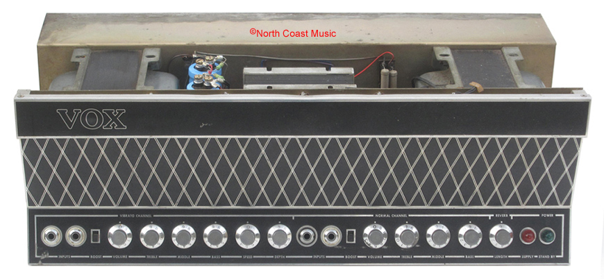
Chassis
The 7120 chassis was comprised of three parts. The chassis base was a rectangular steel box with an open bottom. It enclosed the preamp circuitry. The steel upper chassis was riveted to the base. It was formed to create an electronically shielded "valley" to mount the transformers, choke and other power supply components. The upper chassis then extended over the top of the KT88 output tubes, serving as a heat shield for the cabinet. An anodized aluminum front panel completed the chassis. It included the control panel and front escutcheon and was fastened to the base and upper chassis.
Transformers
The 7120 power transformer, output transformer and the choke for the power supply were all manufactured for Vox by Drake.
|
|
 |
 |
|
7120 Power Supply Components
The 7120 power supply included the power transformer, the choke, the power supply tag strip and a number of filter capacitors.
The "primary" side of the power transformer connected to the wall current. The primary had five input "windings" that allowed the 7120 to operate on 115VAC, 165VAC, 205VAC, 225 VAC or 245VAC mains voltages. The correct mains voltage was manually selected from a five position rear panel rotary switch.
Four "secondary" power transformer windings connected to the internal circuitry of the 7120. One winding provided ~25 volts to power the solid state preamp. A second winding was used in the bias supply for the KT88 power tubes. A third winding supplied 6.3 VAC for the tube heaters and lamps. The fourth winding provided ~600VAC for the B+ supply to power the tubes.
|
|
B+ Power Supply
A typical B+ power supply begins at the "HT" winding on the power transformer. The HT winding steps up the local line voltage to 300 to 450 VAC or even greater. This voltage is passed through a rectifier to change it to DC (direct current). On some amps, this rectifier is a tube, such as the GZ34 used in the Vox AC-30. In other amps, such as the 7120, the rectifier is a bridge of four diodes. However, the voltage from the rectifier is not yet useful to the amplifier. It needs additional filtering before it can be applied to the plates of the tubes.
A choke and some filter capacitors complete the process of creating a clean and usable B+ DC voltage. Please see Figure 1. In most amplifiers, a large, high voltage capacitor (C1) and a choke are attached to the output of the rectifier. A second large capacitor (C2) may be added on the far side of the choke for additional filtering. This is called a "capacitive input filter" because the current from the rectifier enters the capacitor ahead of the choke.
Prior to the 4120 and 7120, the B+ power supply all Vox tube amps used a version of the capacitive input filter.
The B+ power supply for the Vox 4120 and 7120 reverses the order of the choke and capacitor. The pulsed DC output from the rectifier passes first through the choke and then through the capacitors. This is called a "choke input filter" (see Figure 2). The 7120 and 4120 used this filter circuit because it provided better voltage regulation than the capacitive input supply. This regulation was important due to the high plate voltages found in 4120 and 7120 amps. The 4120 and 7120 may be the only guitar amps in history to use a choke input filter in a B+ power supply.
|
|
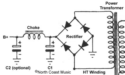 Figure 1 - Typical Capacitor Input Filter B+ Power Supply
|
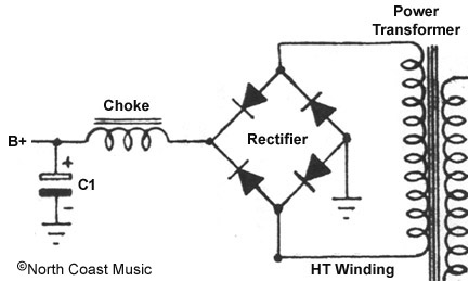 Figure 2 - Typical Choke Input Filter B+ Power Supply
|
|
 |
|
The schematic for the choke input power supply shown in Figure 2 above uses a single filter capacitor. The 4120 and 7120 power supply had two 200 uf 350 volt capacitors (C65 - C66) wired to each other in series. Connecting two 200 uf 350 volt capacitors in series allowed them to act as a single 100uf capacitor rated at 700 volts. This combined 700 volt rating was sufficient to accommodate the ~600VAC B+ winding on the 4120 and 7120 power transformers.
Each of the 200 uf filter capacitors had a 220k one watt resistor (R116 - R117) straddling their positive and negative terminals. These resistors ensured that the ~600 VAC from the power transformer was shared equally between both filter caps. They also served as "bleeder" resistors, discharging potentially lethal stored voltage when the amp was off.
|
60 Cycle Hum
The 7120 and 4120 are noted for their brutish output power. They also are recognized for having a significant amount of 60 cycle hum in their audio output. Let's take a look at the role that the power transformer plays in this hum.
|
A basic power transformer has a primary coil and a secondary coil. The primary coil is connected to the AC from the wall socket, the secondary coil supplies current to the circuitry inside the amp. When AC from the wall flows into the primary coil of the power transformer, a fluctuating magnetic field is created. The fluctuating magnetic fields from the primary coil induce a larger AC voltage into the secondary coil.
In simple terms, if the primary coil has 100 turns of wire and the secondary coil has 500, the voltage induced into the secondary would be five times greater than the primary. Using this example, 120 VAC at the primary will create 600 VAC in the secondary.
Not all of the magnetic fields are contained inside the power transformer. Those that leak outside the transformer can create electro-magnetic interference, or "EMI." EMI is a major contributor of 60 cycle hum in the audio output. As the capacity and voltage of the power transformer is increased, the potential for EMI increases. The 4120 and 7120 have huge power transformers, making management of EMI a greater issue.
EMI interference is often minimized by rotating the placement of the output transformer 90 degrees to the power transformer. The 4120 and 7120 power and output transformers were mounted parallel to each other in the chassis, making the amp more susceptible to 60 cycle hum (see Figure 3). In contrast, the output transformers of most of the other 400 and 700 Series amps were rotated 90 degrees to minimize hum (see Figure 4).
|
|
|
|
|
Figure 3 - Power and Output Transformer Orientation - Vox UL7120
|
|
|
|
Figure 4 - Power and Output Transformer Orientation - Vox UL730
|
|
|
|
EMI interference can also extend to the chassis of the amplifier. Stray magnetic fields from the power transformer can induce a sixty cycle "eddy current" into the steel chassis. These eddy currents may induce hum into the audio output of an amp. The close proximity of the power transformer to three sides of the 4120 and 7120 chassis magnified the possibility of hum producing eddy currents.
|
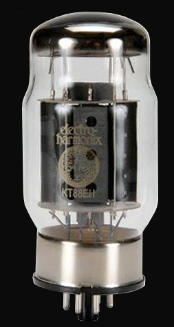 KT88 Tube KT88 Tube
|
KT88
Noted for its high power, low distortion and wide frequency response, the KT88 tube was favored by many top end manufacturers of hi-fi equipment. McIntosh introduced their legendary MC275 audiophile power amplifier in 1961 with four KT88 tubes in the output section.
The KT88 was introduced in 1956 by the General Electric Company plc (GEC), an electronic engineering firm in the UK. It was initially produced by Marconi Osram Valve, a subsidiary of GEC. The KT88 was similar to the American designed 6550 tube but the KT88 offered lower total harmonic distortion.
7120 Power Amp
The Vox 7120 featured four KT88 power tubes in a Class AB parallel push-pull (PPP) circuit. Two KT88 tubes were wired in parallel to amplify the original audio wave while the other pair of parallel connected KT88 tubes amplified an equal but inverted audio signal. The signals from the opposing pair of KT88 tubes were joined in the output transformer.
While the KT88 could accept plate (anode) voltages up to 800 volts, Vox took a more conservative route for the 7120. The 7120 choke input power supply supplied ~600 VDC to the plates of the KT88 tubes, yielding a clean 120 watt RMS output. The legendary Marshall Major amp head would utilize four KT88 tubes with a much larger plate voltage to generate a somewhat overdriven 200 watt RMS.
|
|
Four controls for adjusting the KT88 bias voltage were located just behind the output tubes. These controls, in conjunction with the bias winding on the power transformer, a BY100 diode plus capacitors C69 and C72 constructed the negative bias supply for the 7120. In later 7120 production, the number of bias adjustments was reduced from four to two. 7120 amp head serials started at #1001, serial #1056 still had four bias pots.
ECL86 and the Floating Paraphrase Phase Inverter
The 7120 power amplifier also included an EL84 and an ECL86 tube. While the EL84 was common to Vox amplifiers, the ECL86 was not.
The ECL86 was a dual element tube that included a triode and pentode. The triode section (V1a) was essentially one half of a 12AX7 while the pentode section (V1b) was equivalent to an EL84. This dual function design allowed the triode section of the ECL86 to act as a preamp and the pentode section as a power amp in many 1960's era table top AM-FM tube radios.
In the 7120, the pentode portion of the ECL86 and the EL84 combined to become a "floating paraphrase phase inverter." This inverter circuit converted the audio signal from the preamp into equal but opposite waveforms to supply the "parallel push - pull" KT88 powered output stage.
The triode portion of the ECL86 served two purposes. Initially, it served as a gain stage for the audio signal from the solid state preamp section. Secondly, it incorporated the negative feedback signal from a special winding in the output transformer back into the audio signal path. This negative feedback loop was designed to minimize audio distortion and to maximize the linearity of the 7120 power amp section.
It is interesting to compare the power amp stage of the amp that defined Vox tone, the AC-30, with the 7120. The AC-30 used four EL84 small bottle, low power output tubes in a cathode biased circuit with no negative feedback. The 7120 used four KT88 big bottle, high power output tubes in a fixed biased circuit with an abundance of negative feedback.
|
3_Footer

Photos and editorial content courtesy Gary Hahlbeck
Any and all material presented herein is protected by Copyright.
© 1998 - 2026 The Vox Showroom, all rights reserved
The images and editorial content in this web site may not be copied or reproduced
in online auction sites such as eBay, Reverb and Craig's List. Sellers may provide a link
to the Vox Showroom web site if they wish to refer to this copyrighted material.
|
URL: https://www.voxshowroom.com/uk/amp/7120_hood1.html
|